
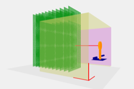
Red Earth was engaged to design a test system for measuring the air flow from various fan units. The system comprised two main parts: the sensor frame, and a test system that would be housed in the control room.
The sensor system is a cartesian three axis linear actuator design (3m x 3m) with a sensor arm with high precision air flow sensors. The sensor arm can be moved in three axis and rotated to a position for obtaining measurements. This is controlled by the test rig that houses the linear actuators controller and communicates with the air flow sensors.
The test system supplies the correct supply current and voltage to the UTT (Unit Under Test) using a programmable single-phase AC PSU. The power used by the UUT is analysed during the test phase via a power analyser.
The software comprises a GUI (Graphical User Interface) application written in C#/WPF to allow the operator to visualise the test measurement positions in a real-world scenario. The application also communicates to all the controllable H/W devices.
